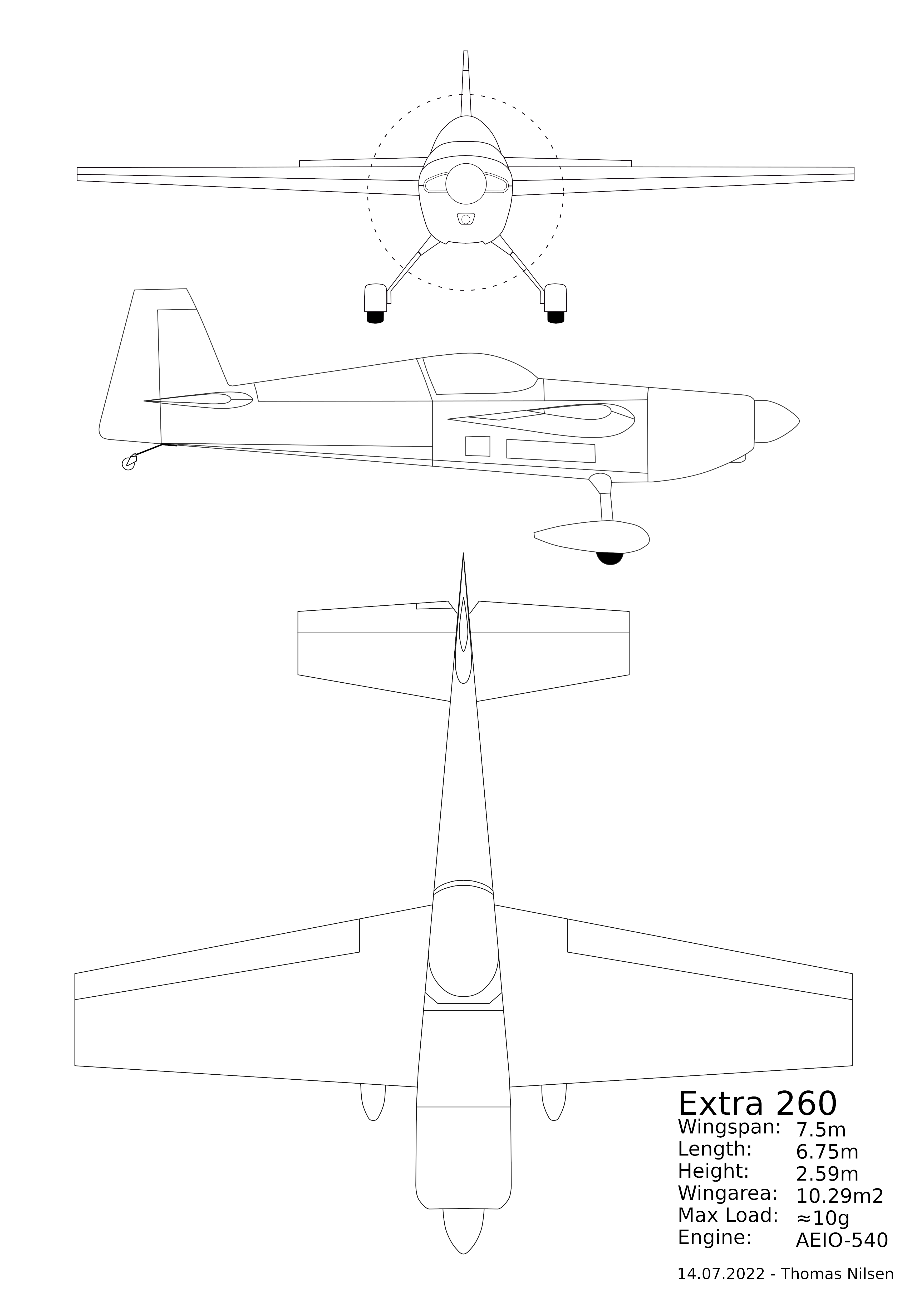
I’ve been unable to find a 3-view for the Extra 260 aircraft. The only material available was a 2-view (side and top) that seems to have been based on a picture of an original Extra manuals page. This can be found in the following post on Flyinggiants.com
So I’ve drawn up the following 3-view that I hope others might find useful. The top and side view is based on the already published original 2-view, but with some slight modifications to make sure the various components are sitting in the correct locations. I also used the ExtraAircraft companys own 3-view of the Extra 300S as a reference since the fuselage on the 300S share much with the 260 (with exception of the 300S having a different landing gear, shorter nose, wings mounted lower, different canopy).
The 3-view was used as base for the static documentation for the 2022 FAI F4 Scale World Championship.
I must also thank Steven Carver who flies the G-EXTR in the UK and who helped out with some photos and details. More info on his Extra 260 can be found on https://www.aerobatics4you.com/
Click on the picture below to get the full image (white background). The same PNG with a transparent background or the PDF version can be downloaded from the links at the bottom.
The following article will provide some of the details required to get the Flight Coach system up and running on an Omnibus F4 v3 Pro flight controller and a Neo-M8N u-blox 8 GPS. Please refer to the Flight Coach website for general details on the installation and use of the system.
The Flight coach website gives detailed instructions on how to make the system work on the older Omnibus F4 v3 controller (NOT PRO) which has a slightly different layout. As these are getting difficult to get hold of I have put together this tutorial for those that would like to use the more readily available Omnibus F4 v3 Pro controller. This tutorial will provide some of the details needed to get it up and running for use with Flight Coach. It is not a step by step guide, but should hopefully help anyone wanting to try the Pro controller with Flight Coach.
The main difference between the Omnibus F4 v3 and Omnibus F4 v3 PRO flight controller boards are:
Pro version has a built in BEC and can be run from a 2-4S lipo pack
Onboard current sensor (not really of any use for Flight Coach)
Uses JST-SH 1.0mm connectors (1×6 pin + 1×4 pin connectors required!) rather than servo pins.
When you purchase the PRO FC, make sure you also purchase the 4 and 6 pin JST-SH 1.0mm connectors required for this setup at the same time.
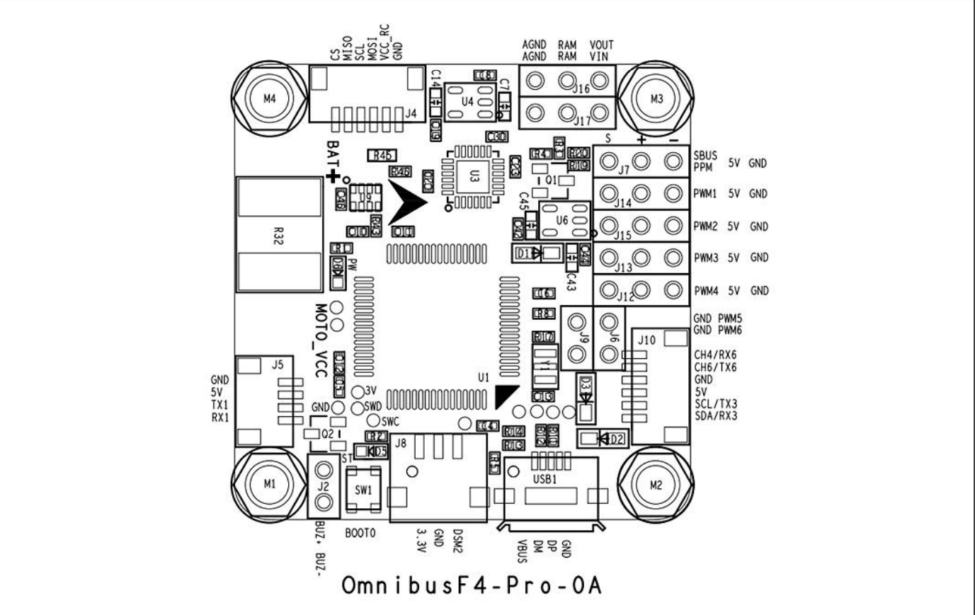
Omnibus F4 v3 Pro Flight Controller
Connections to be used on the flight controller are:
FC Connector
Description
J10 (6 pin)
GPS and compass
BAT+ pad
Input for 2-4s input. Use separate battery or connect it to the flight battery by tapping into the balance connector (keep to it to max 4S, but you only need 2S).
GND pad
Ground connection to battery (underside of the BAT+ pad)
J5 (4 pin)
HC-05/06 Bluetooth Module (optional)
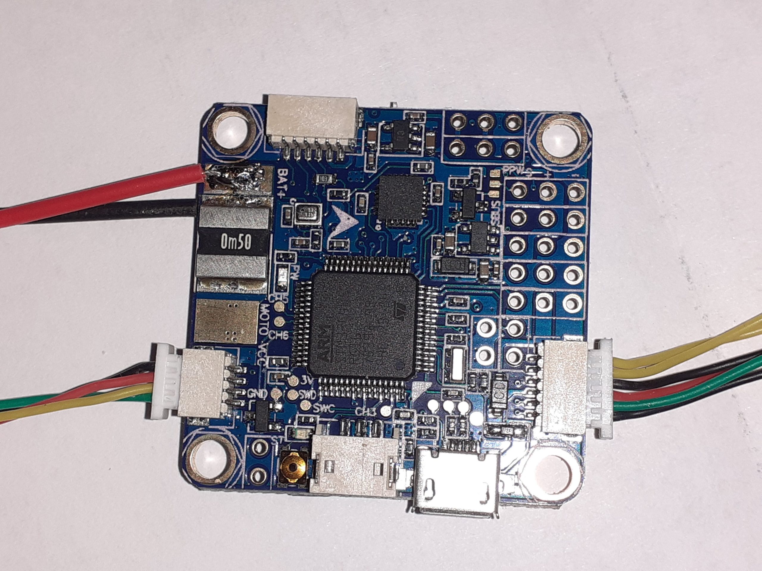
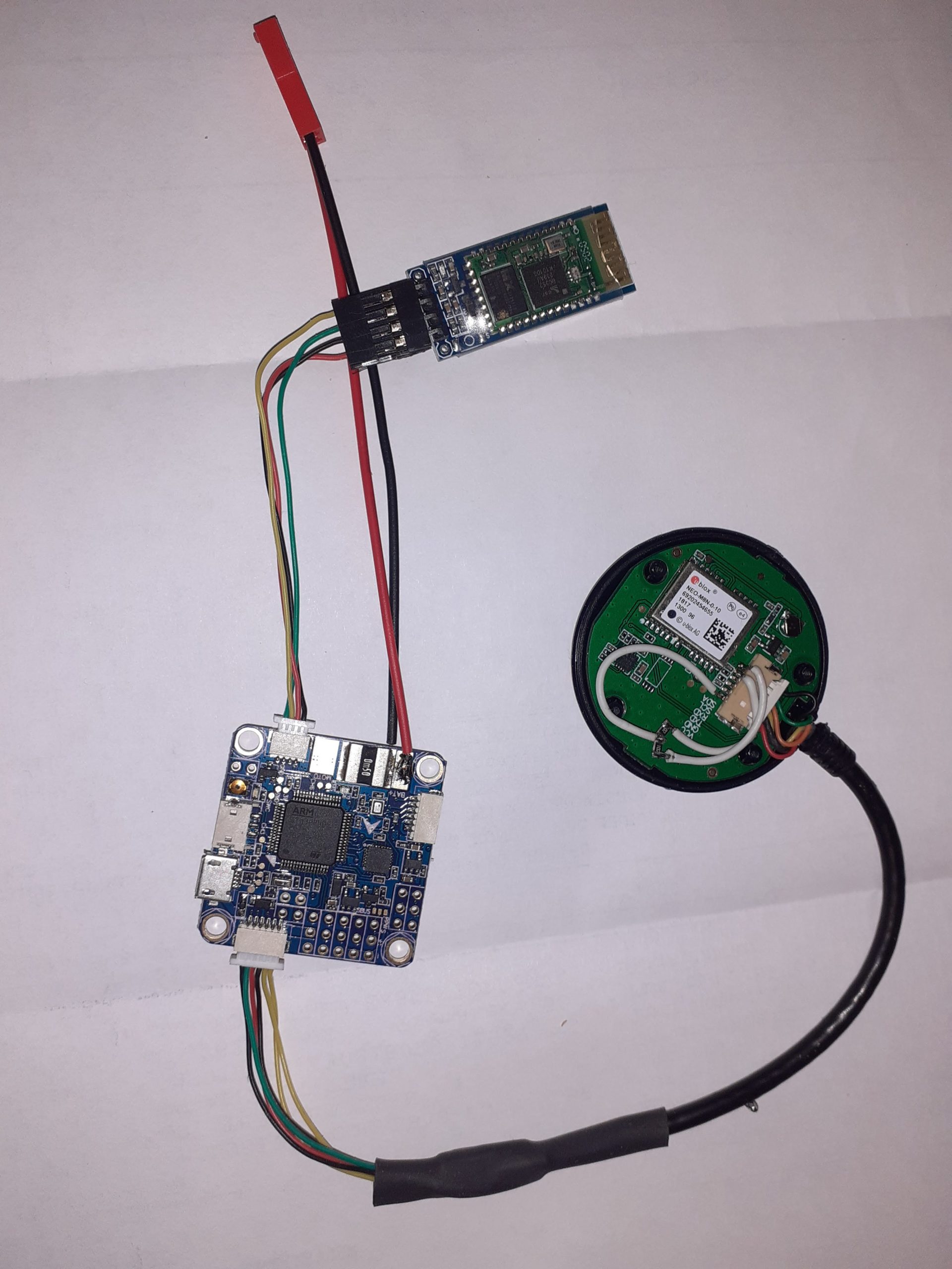
GPS/compass connected to the right, BT module on the left, and the 2S Lipo connector top left.
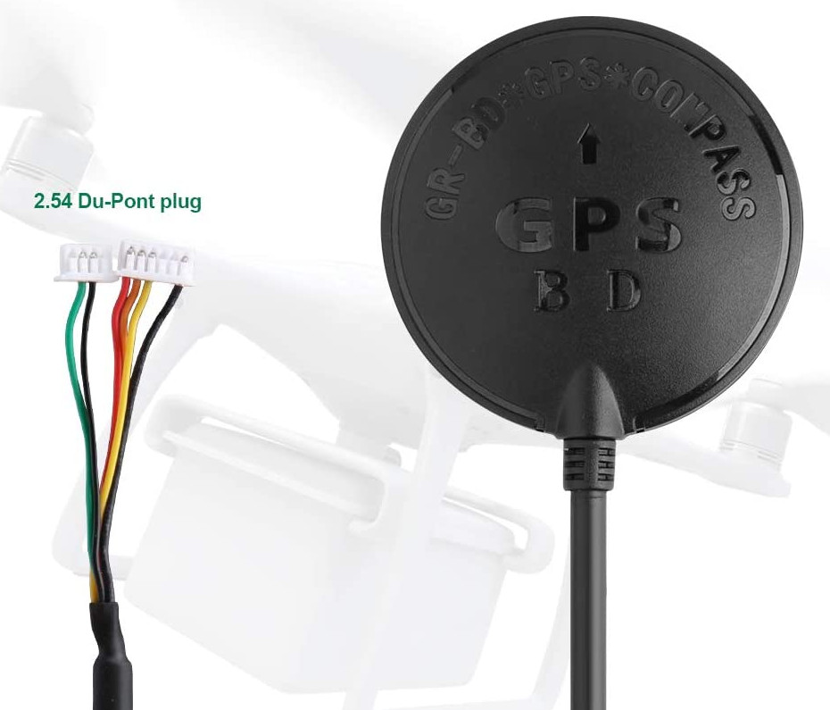
UBLOX M8N GPS Wiring
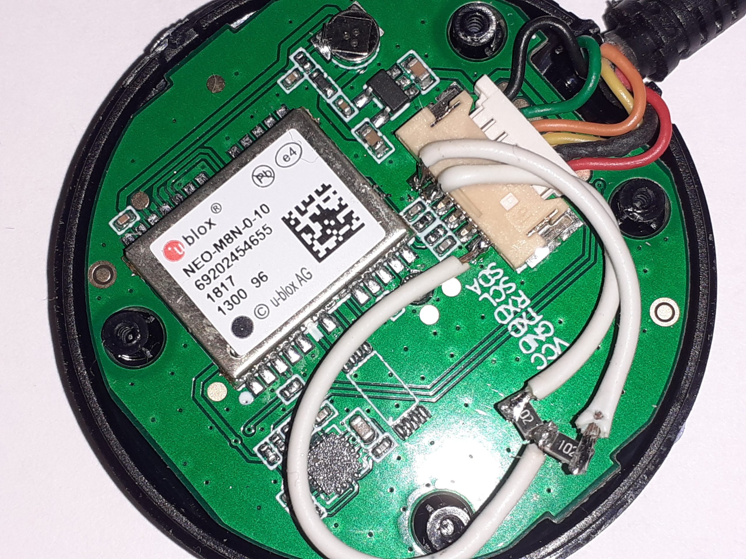
The UBlox NEO-M8N unit combines a GPS and compass and is an affordable and readily available unit. This unit can be found on most online stores selling flight controllers, or from Ebay, Amazon etc. The unit used here is often sold under the label ” BDS GPS” or “UBlox NEO-M8N for PIX PX4”. Any M8N GPS with the combined compass can be used as long as one makes sure the wiring is correct before adding power to the FC and GPS. It might be necessary to open up the GPS plastic casing to see what is what as the GPS board often labels the pins. If no labels are visible then refer to the documentation provided for the specific GPS unit you intend to use.
The wiring outlined below is based on the GPS as pictured above with the same wire colours and two connectors. Since this unit comes with 2.54mm spaced connectors it is necessary to change these to the JST-SH 1.0mm wires, usually by cutting and soldering on a new set of connectors. I have not found any M8N GPS’ that comes pre-wired for the JST-SH 1.0mm connectors.
FC Pins (J10 – UART6)
UBlox GPS Pins
5V
VCC (3.3v – 5.5v) – Red cable on 6 pin connector
GND
GND – Black wire on 6 pin connector
CH4/RX6
TXD – Yellow cable on 6 pin connector
CH6/TX6
RXD – Orange cable in 6 pin connector
SCL/TX3
SCL – Green cable on 2 pin connector for compass
SDA/RX3
SDA – Black cable on 2 pin connector for compass
The compass module in the M8N GPS will not work out of the box when connected to the FC. This is because the I2C bus does not have pull-up resistors and a such the FC will not be able to detect the compass chip. Pull-up resistors will need to be soldered in place somewhere along the wire between the J10 connector and the connector inside the GPS. It is up to the end user to choose where he/she puts these two pull up resistors.
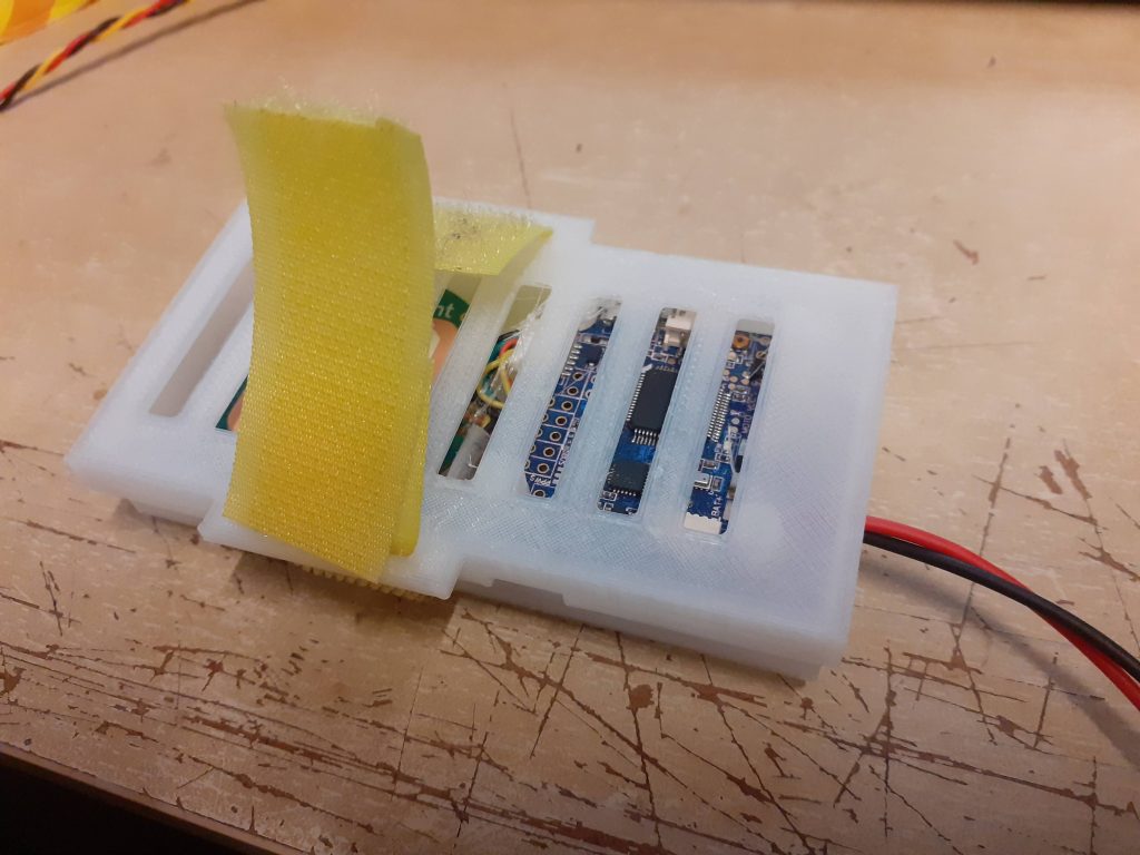
In the picture below one can see how I chose to add the pull-up resistors on the GPS side. This is a bit of a hack job but it works. The soldered wires and resistors will be secured to the PCB with some glue to make sure they don’t come lose during flight. This setup does not allow the original plastic casing to fit any more, but as I will mount the FC and GPS unit in a small 10×4.5cm 3D printed casing it is not an issue.
The principle is that a 1K resistor is added between SCL and VCC, and SDA and VCC. I used some 1206 sized SMD resistors, but one can use any type of resistor as long as it is a between 1K and 2.2K ohm. Some more info and pictures of various methods to achieve this can be found in this iNAV thread on github.com. The resistors can also be soldered somewhere along the wire if that is easier to accomplish as long as they added between the SCL to VCC and SDA to VCC wires.
The white wires and new pull-up resistors are soldered directly to the GPS PCB.
See Update #2 at the end of the article if you want to use a GPS module which doesn’t need pullup resistors.
There are various tools that can be used to upload the firmware. The first time the firmware is uploaded it is recommended to use the DFU method together with the STM32 Cube Programmer available from ST. A detailed guide on how to perform the upload using the STM32 Cube programmer can be found on the Ardupilot site.
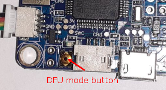
Please note that the FC board will need to be put into the DFU mode in order to upload the firmware. Press the DFU mode button while powering on the board in order to enter the correct mode.
DFU mode button
Once the board is in DFU mode, you should be able to connect using STM32 tool and upload the firmware. Once the new firmware is successfully uploaded, connect the board using Mission Planner or similar software.
Bluetooth Module
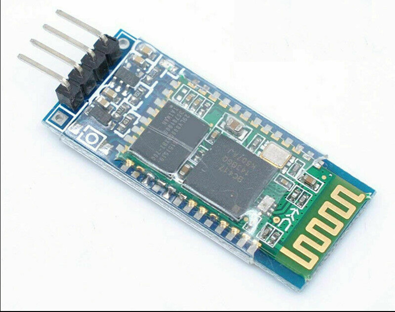
A bluetooth module is not a requirement but makes life easier as you won’t need a laptop to calibrate the setup. If getting a BT module, please make sure you get a HC-05 or HC-06 module.
HC-06 BT module
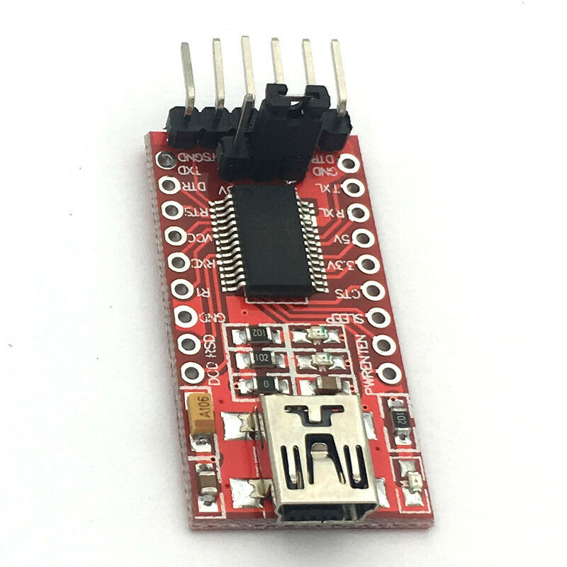
In addition to the HC-05/06 module one will need a device to help program it. This can be an FTDI, an Arduino board or other TTL serial adapter that offers 3.3v logic. I used a cheap USB to FTDI FT232TL adapter which can be found on ebay for very little money.
Usb to TTL FTDI adapter
There are various firmware version for the HC-05 and HC-06 modules, and some of them have different AT command sets. There is no easy way to distinguish a HC-05 from a HC-06, so some trail, error and googling might be needed if you don’t know what you’ve got. The HC-06 module I got, listed a firmware version of 3.0-20170609.
You will also need a serial terminal software to issue the required AT commands once the device is hooked up. I recommend Putty on Windows and Linux, but any software capable of connecting to a serial port can be used as long as its sends a CR and LF control character when pressing the ENTER key. For Linux it defaults to only send CR control character, so to get the LF as well press CTRL+J before hitting enter! Connect using a baud rate of 38400 to start configuring the device.
A HC-05 module will need to be booted in AT mode by connecting the KEY pin to the VCC pin or holding down the button next to the EN pin. The HC-06 moduled does not need to be powered up in AT mode as it will power on as a slave device by default. Power the unit up using a 3.3v FTDI or other serial programming device and start setting the parameters.
To test if you have connectivity with the module, just type AT and hit enter. This should produce an output of “OK” or something similar. If nothing is returned, check the wiring to the adapter you are using and also try and see if it could be an AT mode issue. Some trail and error is to be expected!
I won’t go into details in configuring the bluetooth module, but to get my HC-06 module configured I used the following parameters to set the BT name as “mypilot” and serial port to 57600.
AT+NAMEmypilot AT+UART:57600,1,0
To see which firmware version the unit has, issue AT+VERSION or AT+VERSION? and you should get a prompt with the installed firmware version.
Reboot the BT module and change the baud rate to 57600 in the serial software you are using. Then issue the AT command again to see if it responds. Next try and connect using BT on your mobile to see if the device name you specified in AT+NAME…. is available.
Wiring the BT module with the FC
FC Pins (J5/UART1)
HC-06 Pins
GND
GND
5V
VCC
TX
RXD
RX
TXD
Ready to power on…
At this stage you are ready to try and connect to the FC using Mission Planner or similar software, either by a direct USB connection or using the Bluetooth module.
First thing that should be done is to upload the parameters found on the Flight Coach setup page for the Omnibus F4 V3 card. I have used the same file without issues on the PRO FC.
Download the parameters file from Flight Coach for the Omnibus FC
Connect to the FC in Mission Planner
Go to Config -> Full Parameter List
Click on Load from file and select the downloaded parameters file
When the file has loaded, click on Write Params
With the parameter set, the next step is to calibrate the compass and accelerometer. To complete these steps it is best to have the FC and GPS mounted on whatever you plan to use in your model. This could be a small piece of thin plywood, balsa or a 3D printed casing, whatever you find most suitable.
Start with setting ARMING_REQUIRE in Config -> Full Parameter List to to 1. Remember to press Write Params!
Go to Setup -> Mandatory Hardware -> Accel Calibration and click on Calibrate Accel.
Follow the process as Mission Planner tells you as you go along. It always starts with the FC level.
With the Accelerometer calibration complete, proceed to Setup -> Compass
Detailed instructions on how to do the compass calibration can be found on the Ardupilot site, but one basically just need to move the unit around all its axis a few times. This is the initial step as outlined by the Ardupilot documentation:
“Hold the vehicle in the air and rotate it so that each side (front, back, left, right, top and bottom) points down towards the earth for a few seconds in turn. Consider a full 360-degree turn with each turn pointing a different direction of the vehicle to the ground. It will result in 6 full turns plus possibly some additional time and turns to confirm the calibration or retry if it initially does not pass.”
With the calibration complete, click on the Reboot button.
Reconnect and go to Config -> Full Parameter List and set ARMING_REQUIRE to 0. Remember to click Write Params!
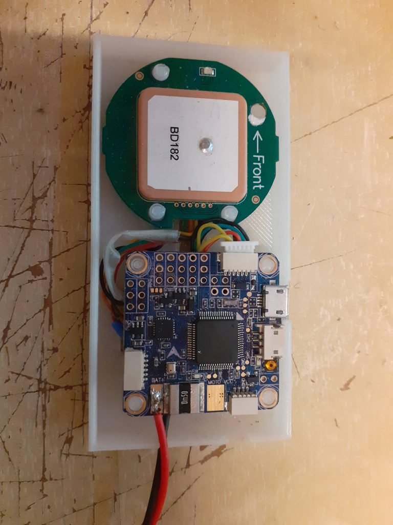
Slot in a FAT32 formatted SD card and go outside and run around on your lawn a few rounds to see if the unit works. Make sure the GPS light is blinking if using the BDS GPS, which indicates GPS lock. Hopefully it should record a log file to the SD card which can be uploaded to the Flight Coach site and rendered in the viewer. If this works you can mount it in your model and take it to the field for a test.
Everything wired up and ready to be tested.
Update #1 – Flight tested
The setup has been tested and is working as expected. Had three flights which logged data without any issues. I have also put the controller and GPS into a 3D printed case. If you would like to use the same case, the STL file can be found below.
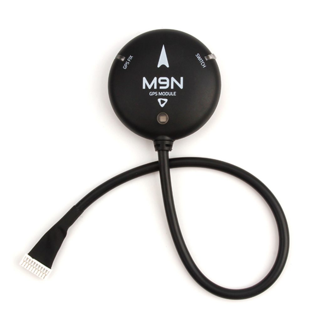
Arnstein Solberg has confirmed that the Holybro M9N GPS can be hooked up without the need to add pull resistors. The connector will still need to be changed as it comes with 1.25mm spaced connctor.
Holybro M9N GPS
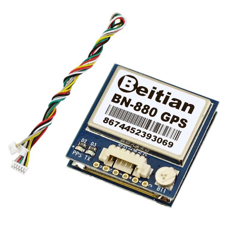
I believe the Beitian BN-880 GPS & Compass Module can also be hooked up without any needs for pullup resistors (I’ll get this confirmed some time in the near future).
Breitian BN-880 GPS module
If you find error/mistakes/mishaps/bugs in this article, please feel free to drop me a note via email or Facebook.
This is a small electronic project Vollrathd on RCGroups came up with a while back. All credit to this project should go to Vollrathd!
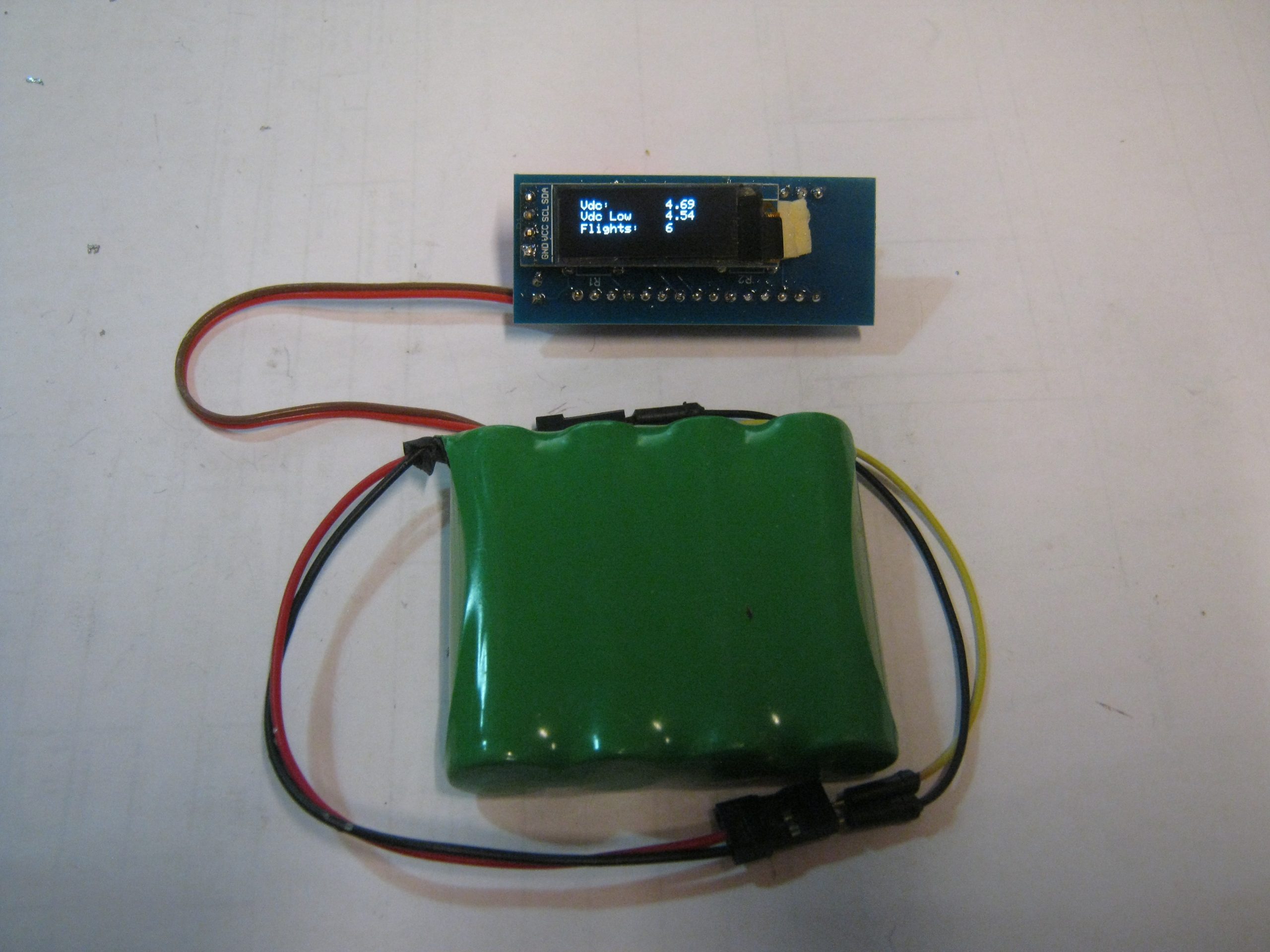
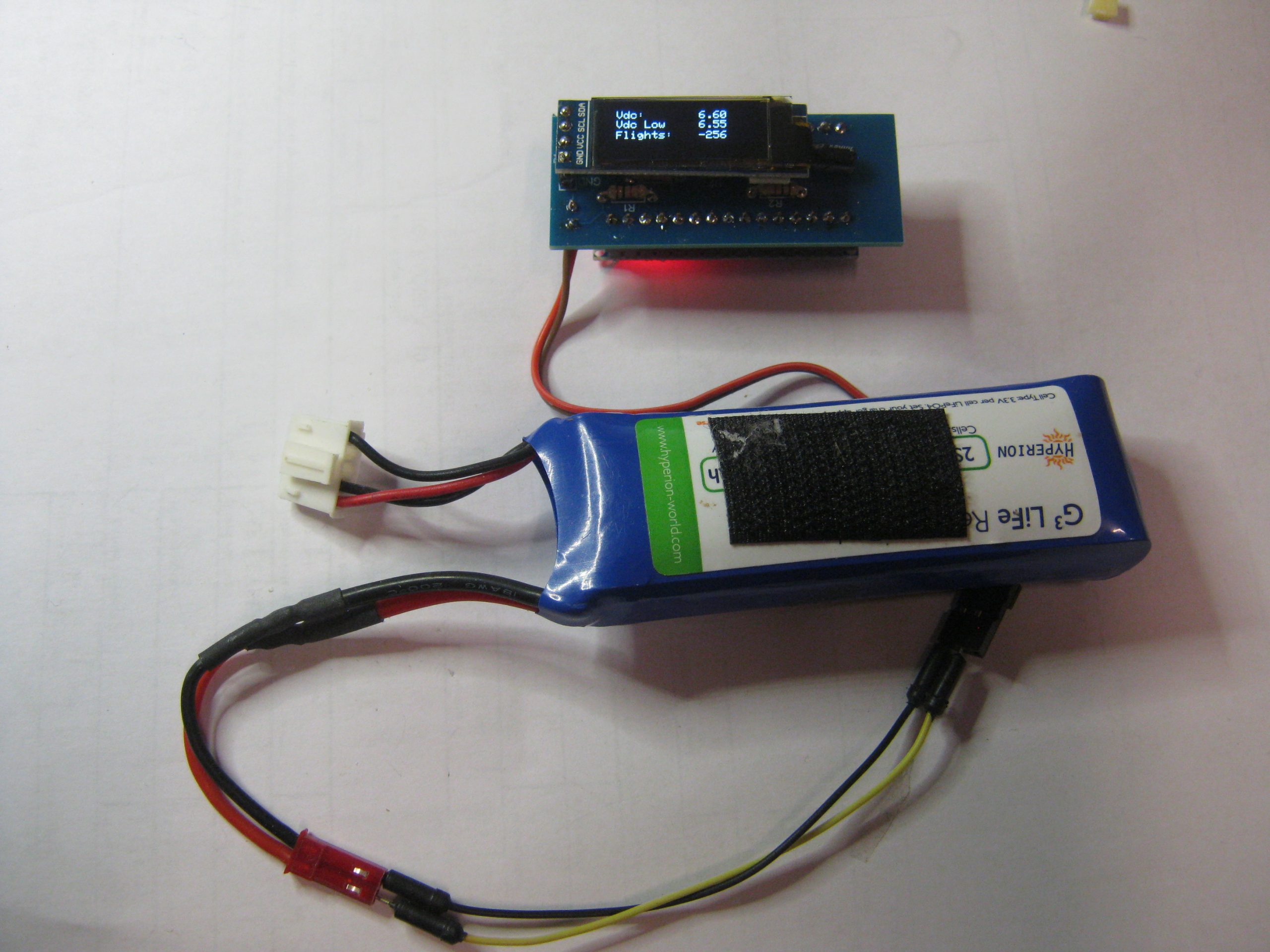
This little battery monitor can be quite handy for many pilots, even those who already have RX battery status via Telemetry as it will sample the battery status 5000 times per second and records the last minimum voltage found. Tests have shown that telemetry capable systems don’t always tell you the entire truth when showing the minimum voltage from the RX side, and it might even cause the loss of a model at some point..
With this little device you can be sure to know what the lowest value the RX pack went to during a flight.
The code here is just a slight modification to the original code from post #289 on the thread, which added support for and OLED screen. The revised code documents how to perform the calibration.
In order to build this little device, the following items are needed.
1x Arduino Nano (both 3.3v and 5v version will work)
1x TL431 ADJUSTABLE PRECISION SHUNT REGULATOR
1x OLED 128×64 display (4 pin version)
1x 3.3K Ohm resistor
2x 1K Ohm resister
1x 47uF capacitor (ceramic or electrolyte)
1 x 10uF capacitor (ceramic or electrolyte)
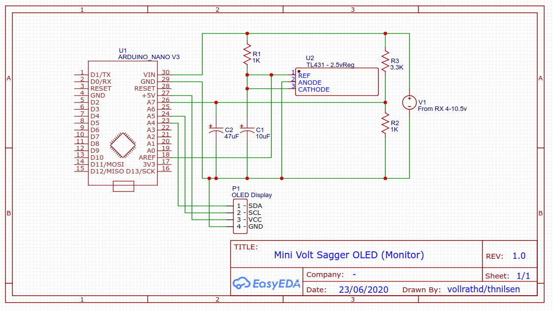
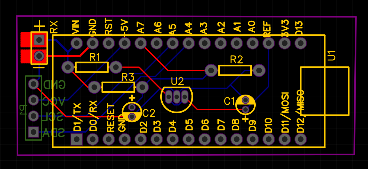
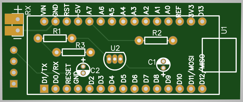
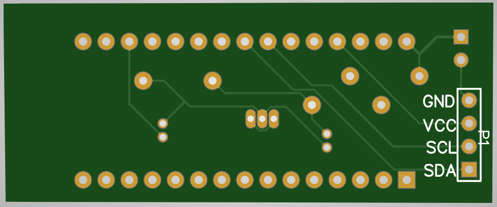
The device can be built by soldering the various parts directly to the Arduino Nano, but it will make it easier to use a PCB prototype board or the custom built PCB design that I’ve put together.
The PCB design will allow you to solder up the device without much effort. A small solder tip is required to solder the components as space can be a bit tight between the component.
My version of the schematic and PCB design can be found on my EasyEDA profile.
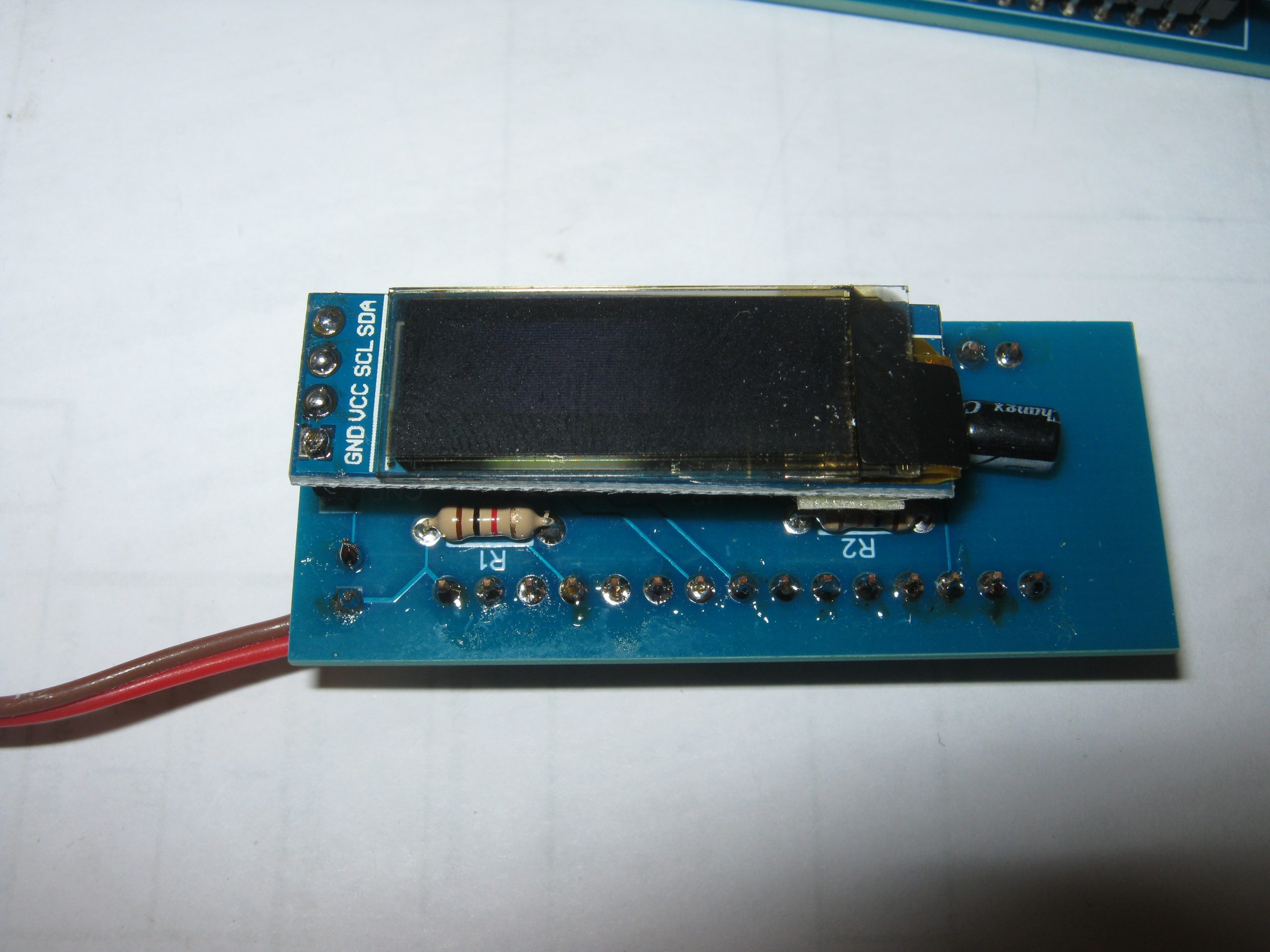
Schematics for use with OLED screenFull layersPCB TopsidePCB UndersideComponents soldered onto the top side of the first prototype PCB.LiFe pack connected up
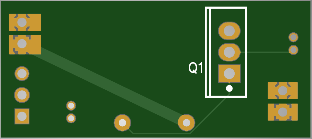
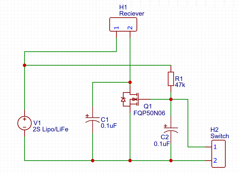
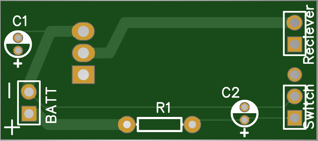
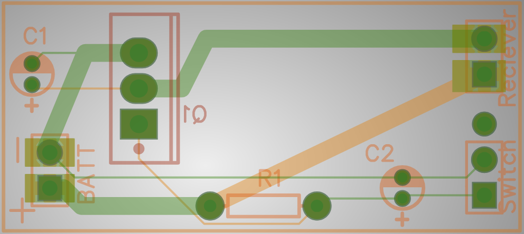
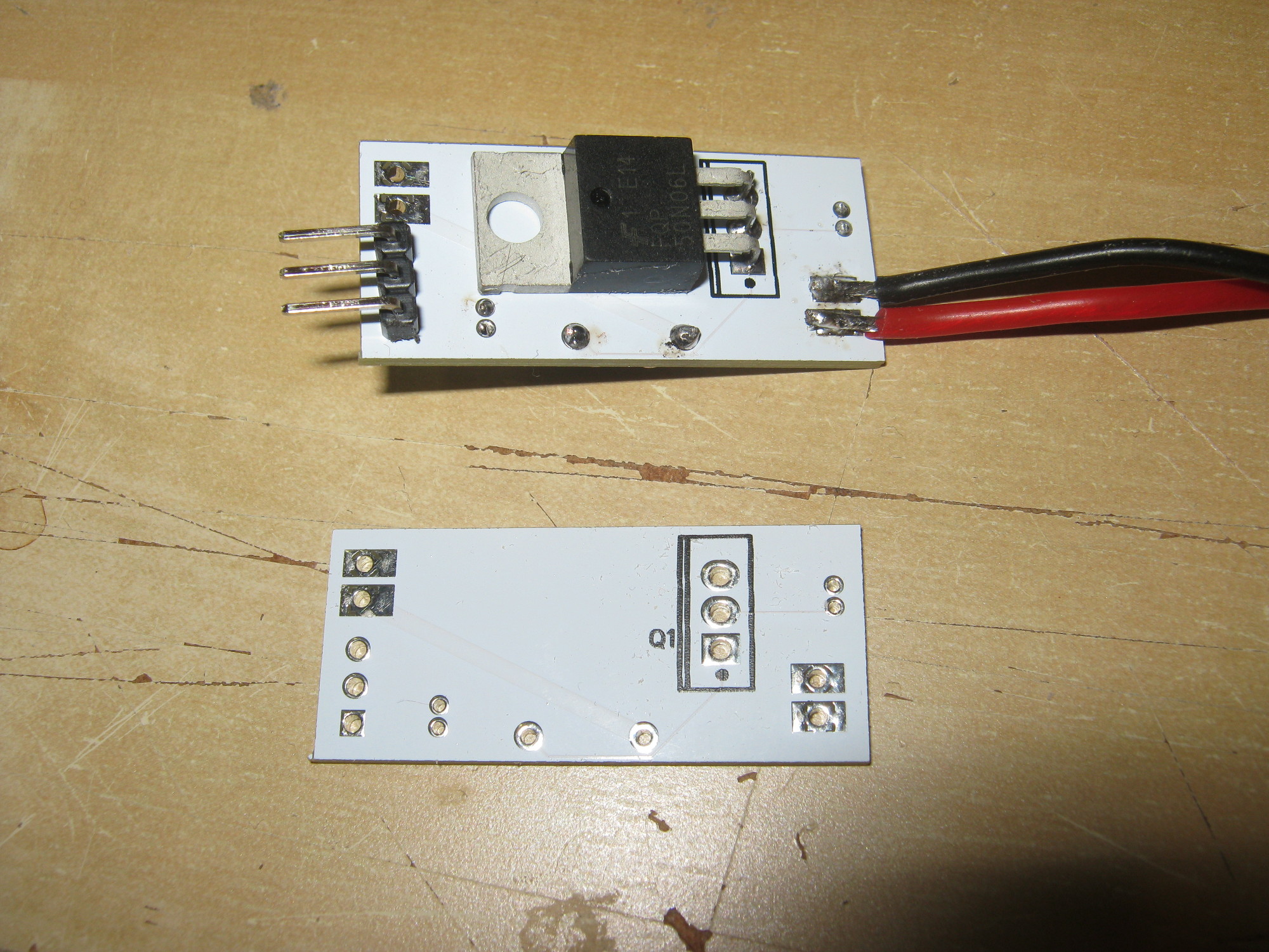
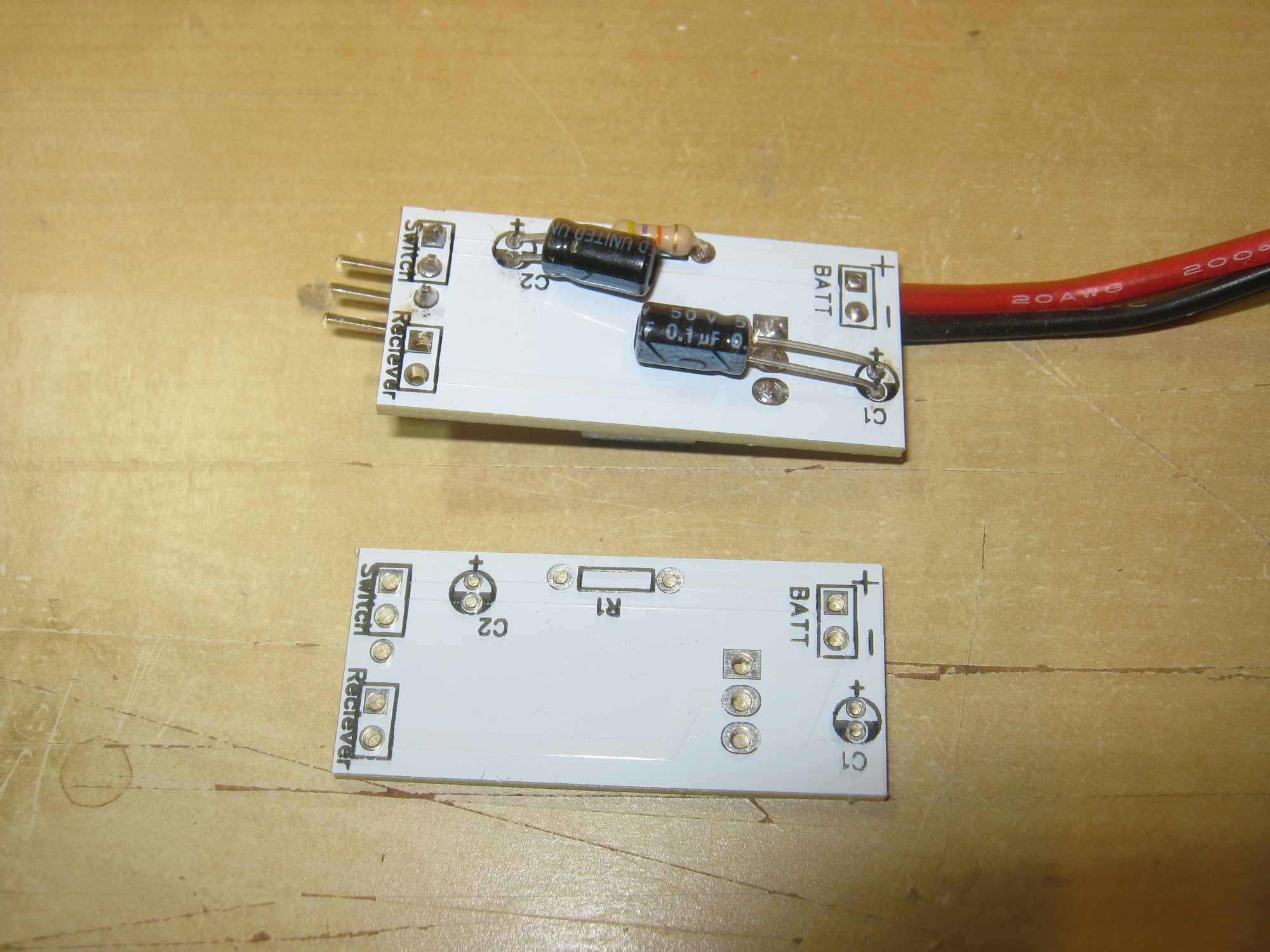
Electronic RC switch to remove the potential fault of mechanical RC switches used in RC planes. This uses a few components to build up a simple but effective circuit.
The circuit is based on the work of Denny Vollrath on RCGroups.
Components required:
1 x MosFet transistor – FQP50N06L 2 x 0.1uF ceramic capacitor (alternatively electrolyte) 1 x 47k resistor 1 x on/off switch or wire to shortcut pins 2 x servo eller battery connector wires
If you like to print your own PCB based on this design please download the Gerber file